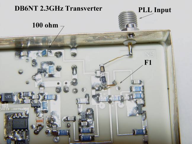

Application Note 004Interfacing the Model 1152 to the DB6NT 2.3 and 3.4GHz TransvertersInterfacing the Model 1152 Phase Locked Oscillator unit to the DB6NT 2.3 GHz and 3.4 GHz Transverters proved to be easy. This application note details the steps necessary to perform this conversion. The DB6NT 2.3 GHz Transverter.... The Model 1152 is injected into the last multiplier by connecting to the top coupling capacitor which is connected to the secondary of Filter F2. An approximate 7.5dB attenuator was required to bring the drive level from the Model 1152 to the right power level necessary to drive the last multiplier stage. The attenuator is a "T" type pad with the two series resistors equal to 20 ohms and the parallel resistor equal to 47 ohms. There is no coupling capacitor required because the Model 1152 is already a capacitor coupled output. So the SMA connector can be directly coupled the one side of the "T" attenuator and the other side of the attenuator is connected to filter F1. Measurements made before and after on Noise figure and Receive Gain indicate that the same values were achieved after the conversion. The photo shows the conversion and where the SMA connector was placed to couple into filter F1. The
connecting wires I used are gold plated ribbon lead between the SMA connector and the attenuator, and
the attenuator and filter F1. The 47 ohm attenuator resistor has it's ground end soldered to the nearest
ground point on the chassis.
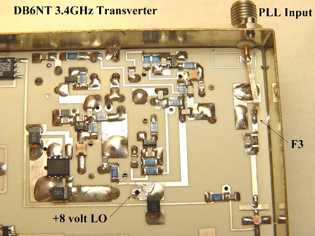
Because the LO chain is all powered from the same +8 volt regulator, it was necessary to remove the 100 ohm resistor that powers the crystal oscillator section to shut it down. You can see the 100 ohm resistor in the upper left corner that has been lifted up at a 45 deg angle to remove one end. The DB6NT 3.4GHz Transverter... The Model 1152 is injected into the last multiplier by connecting to the coupling capacitor which is connected to the secondary of Filter F3. No attenuation was required to bring the drive level of the Model 1152 to the right power level necessary to drive the last multiplier stage. There is no coupling capacitor required because the Model 1152 is already a capacitor coupled output. So the SMA connector can be directly coupled to the output side of filter F3. Measurements made before and after on Noise figure and Receive Gain indicate that the same values were achieved after the conversion. The photo shows the conversion and where the SMA connector was placed to couple into filter F3. The
connecting wire I used is a piece of silver plated ribbon lead between the SMA connector and the output
side of filter F3. You will also notice there is a little "snow flaking" on the input to the multiplier.
It was found during the conversion process that the multiplier required a little tuning to improve the
power output driving the mixer stage. This is probably due the fact that the multiplier is now being used
as a X3 multiplier instead of a X4 previously. Your unit may or may not require this tuning.
The main LO chain is all powered from an +8 volt regulator, while the last multiplier stage is power from a seperate +5 volt power source. So it became easy to power down most of the LO chain by un-soldering the +8 volt section from it's regulator. The photo shows the pin for the +8 volt regulator un-soldered and pulled out of its hole. The last multiplier is still powered by it's own regulator. I want to thank Bruce Wood, N2LIV, for the loan of his 2.3GHz and 3.4GHz Transverters to perform this conversion.
Jerry Mulchin - N7EME
|
|